111 Introduction A worm gear is a cylindrical helical gear with one or. It does not cover helical gears used as wormgears.

Worm Gear Design Calculation Pdf Merge Peatix
DG Pitch circle diameter of the worm gear.

. It consists of worm and worm wheel. We will use the term Pitch P for both the pitch in this tutorial. Let l Lead of the worm and.
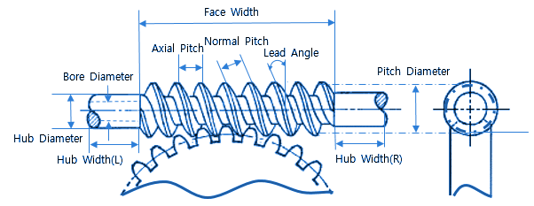
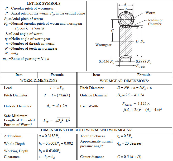
Worm gear design procedure pdf Written By weckwerth Wednesday March 23 2022 Add Comment Edit Running a worm gear set with the gear worm wheel as the input member is corn-monly caUed back driving Back drive effi-ciency of a worm gear set is lower than its forward drive efficiency. Things should be made as simple as possible but no simpler This book is an attempt to apply that principle to gear design by presenting information from a manufacturing point-of-view rather than a theoretical one. P Circular pitch of wormgear P axial pitch of the worm P x in the central plane P x Axial pitch of worm P n Normal circular pitch of worm and wormgear Px cos λ P cos ψ λ Lead angle of worm ψ Helix angle of wormgear.
Also the module of the worm as well as the gear must be equal for a mating worm and gear. Types of Gears Worm gear sets consists of a helical gear and a power screw worm used to transfer motion between non-parallel and non-intersecting shafts. It covers cylindrical worms with helical threads and wormgears hobbed for fully conjugate tooth surfaces.
Provisional spur gear selection procedure for a. View Worm Gear Design Procedurepdf from ME ME481 at University of San Jose - Recoletos Basak Cebu Campus. Worm gears efficiency and wear resistance are normally lower than these of other types of gears of similar size due to high sliding inherently present in worm gear contact.
We know that linear velocity of the worm vW l. PDF On Mar 4 2020 Khalid Elias Hammo Al-Sheekho published Design of Gear Find read and cite all the research you need on ResearchGate. Rack and Pinion sets a special case of spur gears with the gear having an infinitely large diameter the teeth are laid flat.
To the speed of the worm gear NG in rpm. Design the worm gear if it is made of Phosphor bronze 8. Speed of the Worm N1 20 RPM.
Now lets say we have the following design input. Where n Number of starts of the worm. Where N A and N B speed of the driver and driven respectively and Z A and Z B Number of teeth on driver and driven respectively.
Design procedure for Bevel Gear. A gear can be defined as a toothed wheel which when meshed with another toothed wheel with similar configura-tion will transmit rotation from one shaft to another. The axial pitch of the worm and the circular pitch of the gear must be same for a mating worm and gear.
13 GearsGeneral Chapter Outline 13-1 Types of Gears 13-2 Nomenclature 13-3 Conjugate Action 13-4 Involute Properties 13-5 Fundamentals 13-6 Contact Ratio 13-7 Interference 13-8 The Forming of Gear Teeth 13-9 Straight Bevel Gears 13-10 Parallel Helical Gears 13-11 Worm Gears 13-12 Tooth Systems 13-13 Gear Trains 13-14 Force AnalysisSpur Gearing 13-15 Force. Worm gears are used to transmit power between two non-intersecting non-parallel shafts. Calculation of gear ratio i and pitch angle.
Mathematically velocity ratio VR. The worm is threaded screw and worm wheel is toothed gear. American Standard Design for Fine-pitch Worm Gearing ANSI B69-1977 This standard is intended as a design procedure for fine-pitch worms and wormgears having axes at right angles.
3 Type of Foot is shown below Worm Speed Reducers 50 508 587 71 117 59 43 86 133 111 98 68 81 85 75 60 778 906 683 730 857 603 103 116 84 168 200 140 175 130 154 133 98 64 119 76 51. Select number of teeth on worm. Consulting Table 53 knowing the gear ratio i choose the suitable material.
Gears strength gear trains Original PDF - 13MB Annotated PDF - 13MB 14 Microcontrollers Original Annotated 15 Lab time 16 Sensors Original Annotated 17 Lab time 18 Belts chains cams 19 Quiz 2 20 Lab time 21 Optimization 22 Professional ethics PDF - 13MB 23 Review of festivity procedures. Specify the Lewis form factor for worm gear teeth from Table 10-4 page482 Pdf 498 4 5. DESIGN PROCEDURE FOR.
Equations for American Standard Fine Pitch Worms and Wormgears Per. Flowchart for worm gear designing process. CHAPTER 11 Worm Gears Chapter Outline 111 Introduction 439 112 Force Analysis 446 113 AGMA Equations 449 114 Design Procedure 453 115 Conclusions 455 References 456 Further Reading 456 Nomenclature 457 Abstract Worm and wheel gears are widely used for nonparallel nonintersecting right angle gear drive system applications where a high transmission gearing.
Design of peripheral structures of gears 5. Depending upon the type and accuracy of motion desired the gears and the profiles of the gear teeth can be. Executing the drawings of the parts related to the gears.
The worm wheel teeth envelope the treads on worm which gives line contact between mating. Transmitted Power Input and Output speed Center distance Type of driver and driven load. There are no great advances in gear technology described.
Up to 24 cash back CHAPTER 11 Worm Gears Chapter Outline 111 Introduction 439 112 Force Analysis 446 113 AGMA Equations 449 114 Design Procedure 453 115 Conclusions 455 References 456 Further Reading 456 Nomenclature 457 Abstract Worm and wheel gears are widely used for nonparallel nonintersecting right angle gear drive system applications where a. Gears Engineering and Design. These gears are generally at right angles to each other.
Gear Design National Broach and Machine Division of Lear Siegler Inc. Worm Gear Design The power to be transmitted The speed of the driving gear. 2 Type of Foot is shown on the left hand side of Gear box sketch Principal Dimensions mm No.
Introduction to Gear Design Introduction Albert Einstein once said. A high-efficiency worm-gear speed reducer is desired to accept 20 hp from a 1750-rpm. Design shapes of spur gears 3.
This chapter provides an overview of worms and wheels and outlines a selection procedure. A worm gear drive is used to transmit 22 kW between two shafts which are 225 mm apart. The transmission ratio is 241.
Research into worm gear wear is going on worldwide which is mainly experimental Hoehn l Octrue 2 Octrue 3 Houser 4 Wang 5. Check spur gears strength 4. It is the ratio of the speed of worm NW in rpm.
Machine Design II Module 2-GEARS Lecture 16 WORM GEARS WORKED OUT PROBLEMS Contents. N w N G. 1 Type of Foot is shown below the sketch of Gear box No.
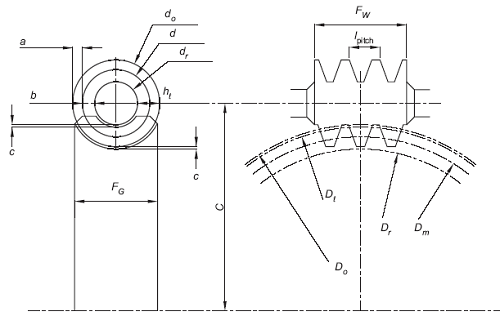
Proportions of worm and worm gear 2. Clarify specifications and determine basic elements 2. In this series we explain how to design gears and peripheral parts according to procedures using simple mechanisms.

Pdf Machine Design Ii Module 2 Gears Lecture 16 Worm Gears Worked Out Problems Contents Aju Joseph Academia Edu
Best Worm Gear Design Calculation Pdf
Agma Worm And Spur Gear Design Equations And Calculators
Worm Gearing Classes Proportions Materials And Worm Gear Cutting

Innovative Design For A Ball Worm Gear Mechanism Semantic Scholar
Agma Worm And Spur Gear Design Equations And Calculators
Worm Gears Roy Mech
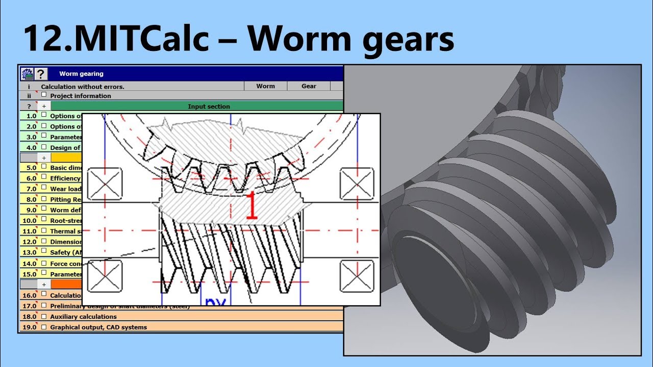
Worm Gear Calculation And Design Mitcalc 12 Youtube
0 comments
Post a Comment